End Fed Half Wave 40-10 Wire Antenna
The solution to improving my send and receive would be making an End Fed Half Wave (EFHW) 10-40 antenna. I want to optimize based on a few things: small lot, low-vertical leeway, nosie neighbors and avoiding the power lines in the backyard, I thought that an EFHW 10-40 wire antenna is the best solution.The plan
Thursday - June 20, 2019After researching the antenna, I devised the first part of the plan – the installation. I'll put the antenna in an inverted-L (slightly sloped) configuration supported by a 20' Jackite Pole on the feed point side and a 30' Jackite Pole at the far end. It would run diagonal, over the roof of the property and perhaps put a couple of kites at the tip of the poles to make them more neighbor friendly :p
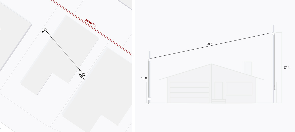
That's just about enough distance if the poles were to fall towards the power line and not have contact. Remember, a half wave is about 67 feet and so the first pole will have to accommodate at least 16.86 feet, based on that illustration.
The shopping list (so far)
- 30' Jackite pole
- 20' Jackite pole
- FT240-43 toroid (3)
- 14 gauge enameled wire (97", about 8' and change).
- Carlon E989NNJ-CAR Junction box 4" x 4" x 2" - Lowes or Home Depot
- 100pF 10KV Capacitor
- SO-239 Chassis mount connectors
- 10-24 x 3/4" hex head machine screws
- #10 flat washers, lock washers, nuts
- #10 wing nuts (2)
- 6-32 x 1/2" pan head machine screws
- 6-32 x 3/4" pan head machine screw
- #6 flat washers, lock washers, nuts
- Solder lugs or ring terminals
- 14AWG stranded copper wire (200 ft?)
Optional
- 1/4" Eyebolt
- 1/4" Nuts, washer, and lock washers
- Wire rope clip M4 (size depends on your antenna wire)
- Wire rope thimble (again size depends on your antenna wire)
- Bud Ventilator NBX-10911
- Krazy Glue
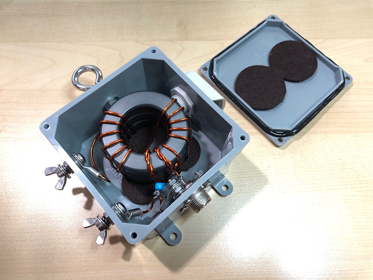
Transformer: Coils in the toroid
Sunday - June 23, 2019An UNUN is needed to match the high impedance of an end fed antenna (2k-4k ohms range). So a 49:1 impedance transformer is needed to match the 50 ohms of the coax at the feed line.
I got three FT240-43 toroids (two would be lighter, but three increases the curie point so it can handle longer duty cycles), a spool of the 14 gauge enameled wire ready, along with Super Glue that I got from Walgreens.
First, I glued the three toroids together. Then, I cut two pieces of wire, 13" and 80". Using a vice grip to pin the two wire ends together, I twisted the short and long wire until about 4" was left in the short wire.
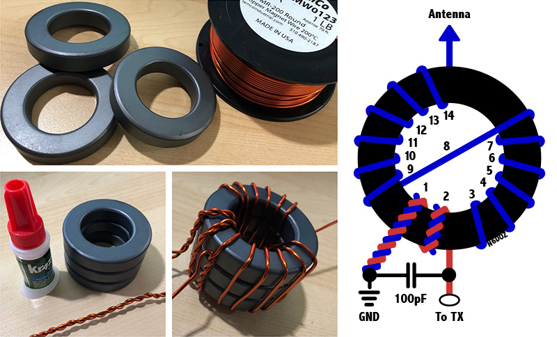
I coiled the twisted part over the toroid—2 turns with the twisted primary and secondary, then continuing the coil until 7 comes around and goes to the other side for the 8th turn. Then continue to turn filling the other half of the surface to 14 turns until the wire comes from the bottom.
This video by Steve can show you what I mean:
The innards and enclosure
Tuesday - June 25, 2019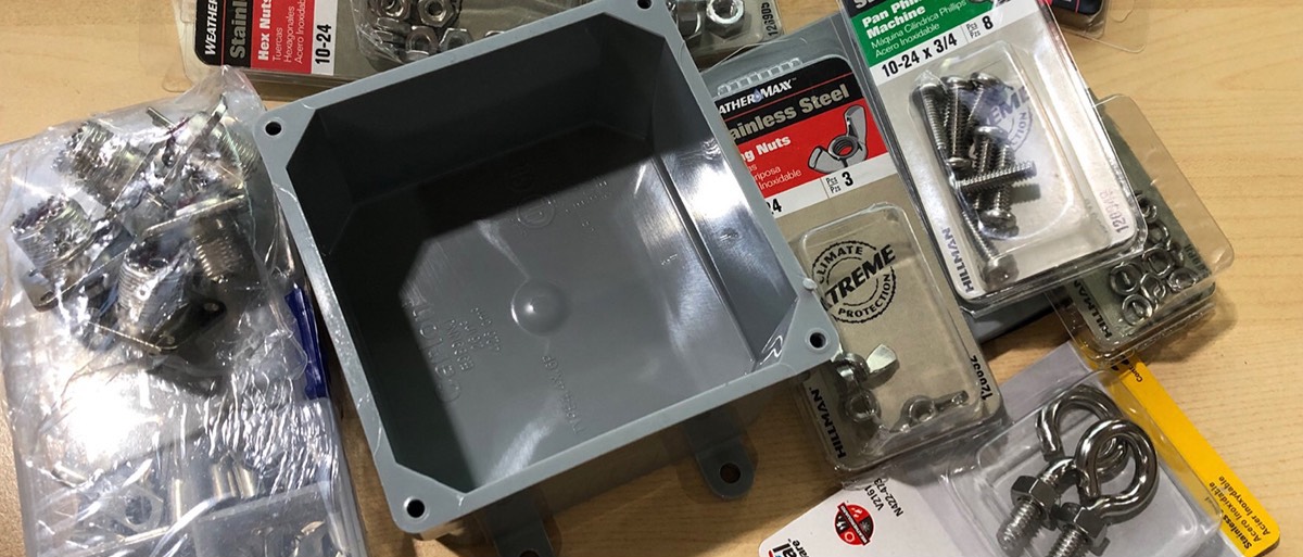
I collected all the required parts and measured distances and bore requirements. After marking were the holes would be, I put a tiny bit on the drill to punch pilot holes which gave me the confidence to go ahead and start drilling to the proper sizes. These bores includes, the eyebolt on top, the vent to the right side, then antenna peg and ground peg on the left, and the SO239 bulkhead coax connector. Oh, I also drilled about 4 weep holes at the corner of the bottom. I used both regular bits and a step drill bit for the bigger holes.
Then I temporarily installed the hardware onto the enclosure so that I can take measurements and cut the copper wire leads on the transformer. After that, I removed the hardware and put them back in with a dab of clear sealant RTV, then installed the hardware back.
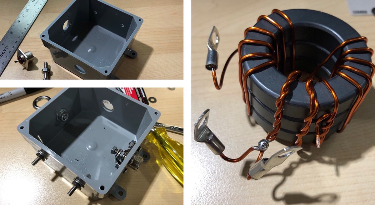
I think the hardest part of this whole thing was next, removing the enamel insulation from the wire leads. I tried sanding it off with sand paper and scraping with a hobby knife but it was too tough. So I ended up using my Dremel which seemed to have done the trick. I tinned and soldered the leads onto terminals.
Before doing anything else with the enclosure, I went ahead and put some furniture leg padding on its floor and lid so something will keep the transformer from moving around. Then I placed the transformer inside the enclosure, bolted down the leads and soldered the primary to the SO239. Last thing, aside from batting down the lid was putting a 100pf 3KV capacitor between the SO239 ground and primary.
And walah!
Up next, install and testing >